LSJ File Demonstration
How to use a lsj (Laser specific job) file to automate a marking process.
In this example, we are illustrating a typical scenario in which an SMC controller is employed to mark a pre-defined image with dynamic data onto a part. The part will be positioned within the marking area using a mechanical stage controlled by a PLC. There will be a SMAPI application overseeing the progress and status of the marking process too.
In the following discussion, we will dive deeper into the process workflow and the roles of each entity in the process.
The Process.
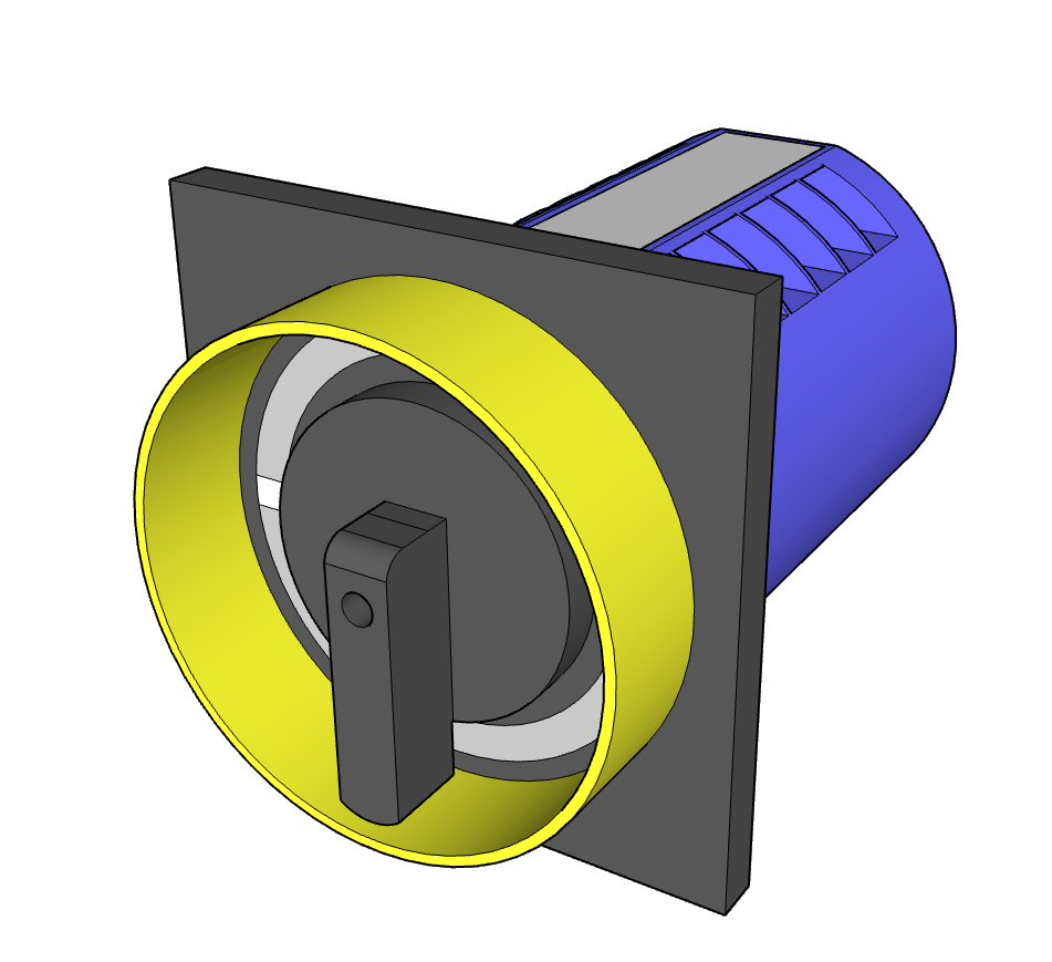
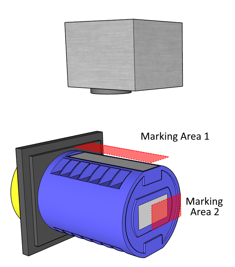
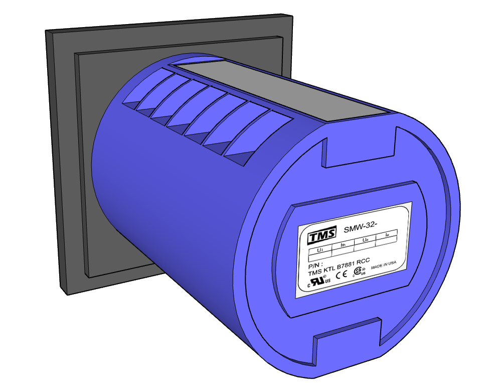
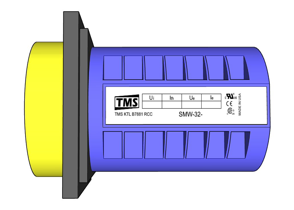
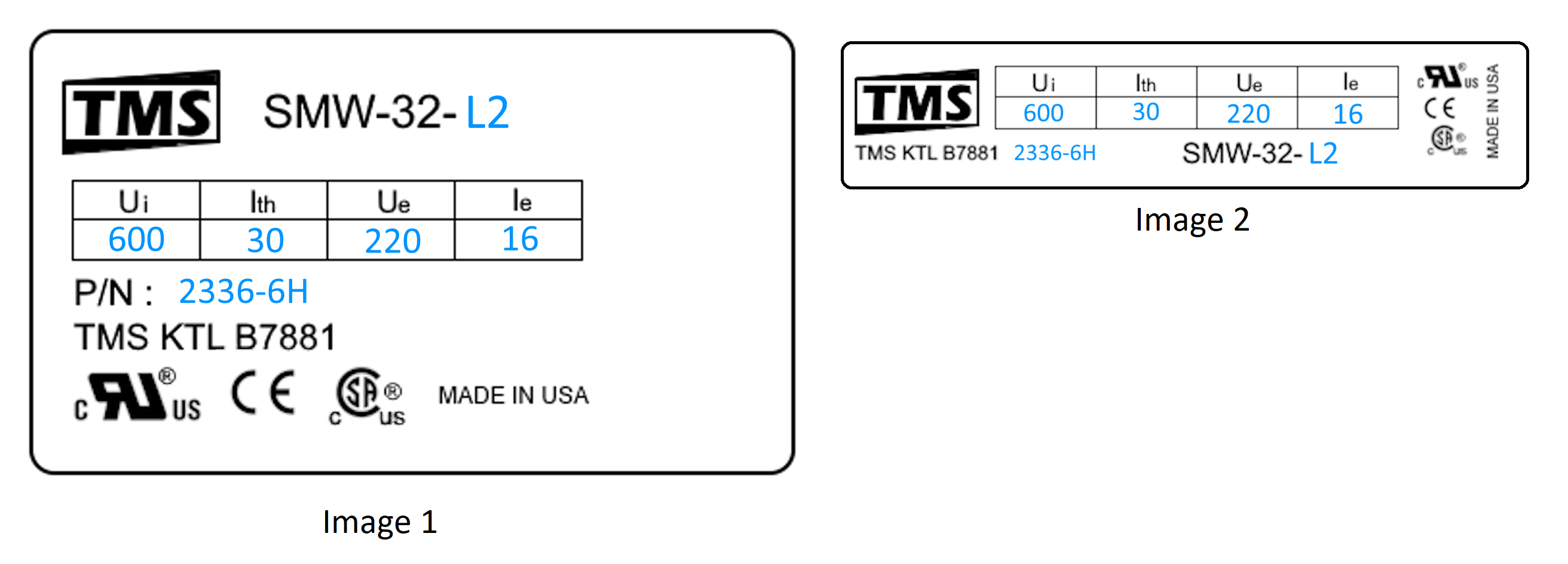
In this process, we will mark two images on an industrial Cam switch.
|
|
The marking images will include electrical ratings of the cam switch, certifications of compliance, and the manufacturer's details.
|

|
|
|
| Image 1 | Image 2 |
There are two images to be marked on each part. For each part number, the ratings will vary. However, the position of the two images will remain the same except for one rating, in which case the position will be adjusted. The ratings and the part number will be matched using a database. For simplicity, we will use a hardcoded table with each row number tied to the part number.
The work flow.
The demonstration system consists of a SMAPI Application, SMC controller, marking system and a PLC to automate the machine.
We assume the following system topology.
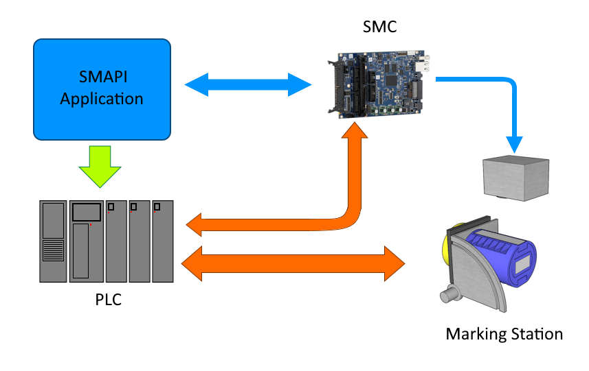
The SMAPI application is used to demonstrate SMAPI's ability to integrate into a larger software control system. It can function as either a standalone application or a subsystem within a larger control application. The application will showcase how to load an LSJ file and adjust the position of an image to meet specific marking requirements. In this example, we will demonstrate a straightforward shift operation for a marking image in the LSJ file.
The PLC will automate the mechanical system and sequence the marking process once it is loaded with necessary information. It will also communicate with the SMC controller to initiate marking and select the correct image for marking.
To begin the process, the operator selects the correct part from the database using the application. The application then communicates with the PLC and the SMC controller, preparing them for the marking process. After this step, the PLC takes control and initiates the process.
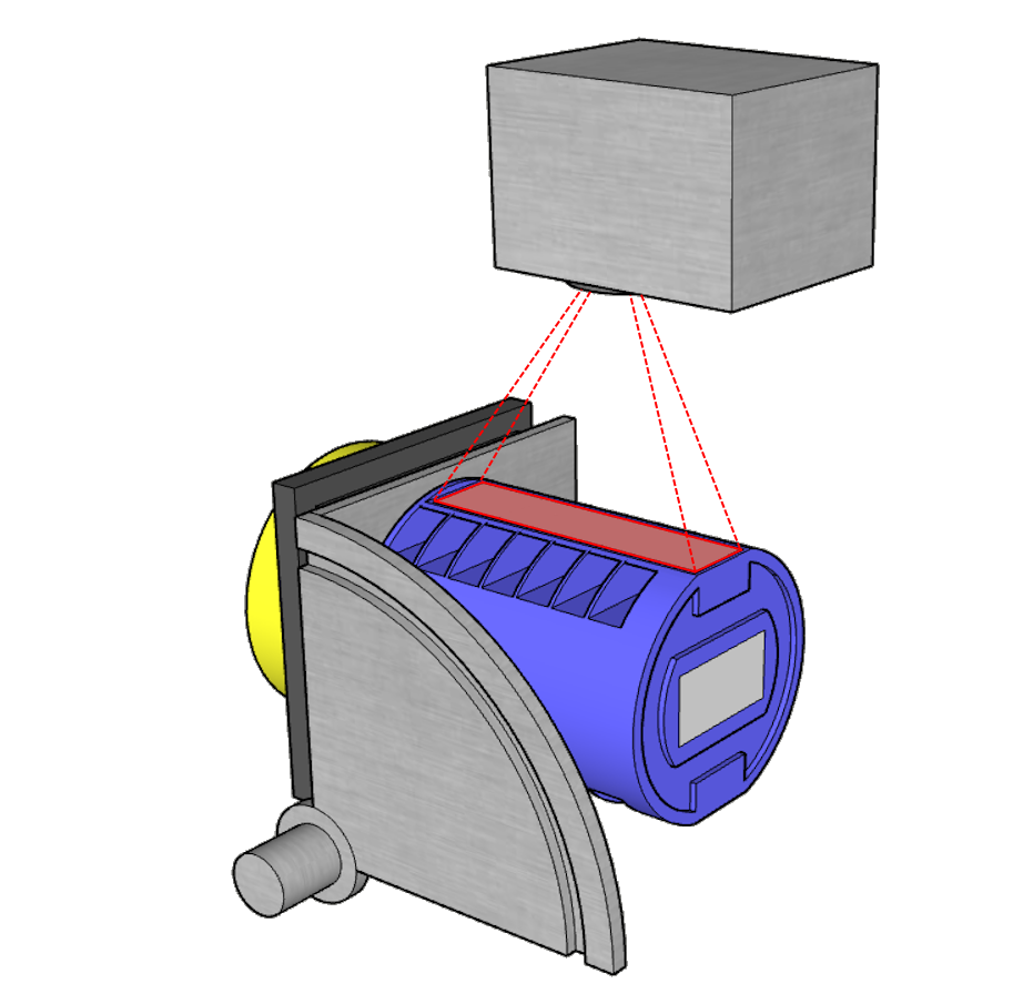
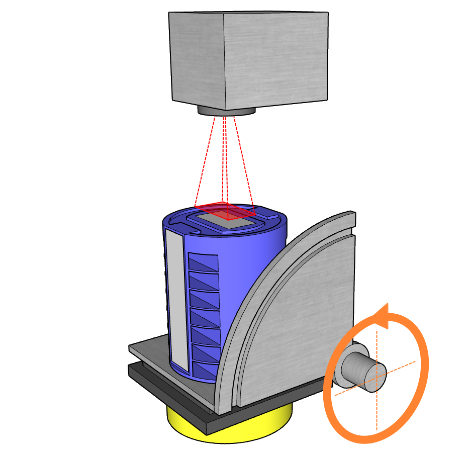
Once the part is securely positioned in the marking stage, the PLC will proceed to align it for marking. It will first position the part to mark the first image and then rotate the stage to mark the second image.
|
|
During each step of this process, the PLC will establish communication with the SMC controller. It will inform the controller which image is ready for marking and instruct it to initiate the marking process using the SMC digital control interface. SMC Controller in return will indicate marking in progress using the same interface, during which the PLC will wait. This synchronized coordination ensures that both images are accurately marked on the part.
The whole operation will continue until all the parts are marked.
PLC and SMC interface
The PLC will use the General purpose Control Signals port ( Connector J16) on the SMC controller to notify the status of the stage.
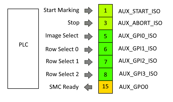
Start Marking – AUX_START ISO
The PLC will assert this pin to initiate the marking process. The PLC will wait for the stage to settle in place before asserting the signal.
Stop operation– AUX_ABORT ISO
Stop the marking operation
Image Select – AUX_GPI0_ISO
The PLC will use this pin to notify which image should be used for the next marking. The SMC will read this pin before marking the image.
Bit value 0 – Select image 1
Bit value 1 – Select image 2
Row Select 0 to 2 – AUX_GPI1_ISO to AUX_GPI3_ISO
The SMAPI application will send this information to the PLC when the user selects the part, and the PLC will set the bits accordingly.
SMC Ready - AUX_GPO0
The SMC controller will assert this signal to indicate that marking is in progress. The PLC will verify the state of this signal before placing the part in the marking area.
Creating the Marking file (LSJ file)
We will first create the two images required for marking in ScanMaster Designer and then add the ScanScript code to interface with the PLC.
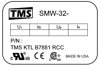
The images consist of static image and dynamic text to fill in the specifications of the part.
In the following image, the blue text represents the dynamic information, while the black color represents the static image.
In ScanMaster Designer, create a project and add two 2D images to it. For each image, add the static images as discussed above. Create dynamic text components and position them over the relevant locations. The dynamic text components will be populated according to the part number selected. For this demonstration, we will use a hard-coded database.
The script consists of a main loop that runs until it receives a stop signal from the PLC. Inside the main loop, the script will wait for the marking start signal to begin marking. Once it receives the marking signal, the script will indicate that marking is in progress, populate the dynamic content, and proceed with marking. Once marking is completed, it will wait again for the next marking signal from the PLC.
Download the sample ScanMaster designer project here.
Saving the LSJ file
"The LSJ (Laser Specific Job) file is a precompiled file containing all the marking instructions that can be used to store and reuse for later use. Since the file is precompiled, all the vector images are converted to laser controller-specific instructions. Therefore, the file does not contain any primitive shape information. However, for visualization purposes, a copy of the primitive shape information could be saved with the LSJ file, which can be used to visualize the content in the file."
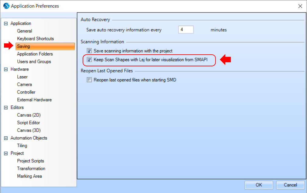
To save shapes with the LSJ file check the "Keep Scan Shapes with LSJ" check box in the application preferences
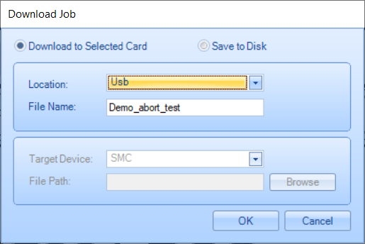
To save the project as a LSJ file, Click the download button on the Home tab.
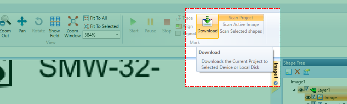
Select where you want to save the LSJ file in the "Download Job" dialog box. You can choose to save the file on the marking controller or in a location on the computer.
ScanScript Sample listing
The ScanScript sample provided here is intended solely for demonstration purposes only.
DBindex = 1
-- Rated Voltage offset of the database row and size
Voffset = 1
Vsize = 3
-- Rated Current offset of the database row and size
Ioffset = 5
Isize = 2
-- Rated Insulation Voltage offset of the database row and size
IVoffset = 8
IVsize = 3

--Create the local Database for marking text lookup
Ratings = Array.StringArray(7)
Ratings[1] = "220,20,600"
Ratings[2] = "220,30,800"
Ratings[3] = "220,40,900"
Ratings[4] = "220,60,900"
Ratings[5] = "460,40,900"
Ratings[6] = "460,60,900"
Ratings[7] = "460,80,900"


-- Function to return Rated Voltage given the Database Row
function GetRatedVoltage(row)
    return String.Substring(Ratings[row],Voffset,Vsize)
end

-- Function to return Rated Current given the Database Row
function GetRatedCurrent(row)
    return String.Substring(Ratings[row],Ioffset,Isize)
end

-- Function to return Rated Insulation Voltage given the Database Row
function GetRatedIV(row)
    return String.Substring(Ratings[row],IVoffset,IVsize)
end

-- Function to read the database index from the General purpose Control port
-- Pin number 1 to 3 will be used to indicate the desired Database row
-- PLC will set these pins active during operation
function ReadDBRow()
    val = IO.ReadPort(Port.Advanced.CurrentDIO)
    val1 = BitOp.BAnd(val,0xE)
    Val2 = BitOp.ShiftRight(val1,1)
    return Val2+1
end

-- Function to Indicate marking in progress
function SetSMCReady(state)
    Io.WriteDigital(Pin.Dout.UserOut1, state,true)
end

-- Set SMC ready Signal to the PLC
SetSMCReady(1)
run = true

while (run) do
    --Wait until the Start Marking pin is set by the PLC or abort
    waitforRun = true
    while (waitforRun) do
        statRun = IO.ReadPin(Pin.Din.AuxiliaryStart)
        statAbort = IO.ReadPin(Pin.Din.Abort)
        if(statAbort) then
            waitforRun = false
            run = false
            break
        elseif(statRun) then
            waitforRun = false
            break
        end
        Sleep(100)
    end

    -- Abort Check
    if(run) then
        -- Set SMC Busy signal
        SetSMCReady(0)

        -- Read the database index Using the user port pin 1 to 3
        DBindex = ReadDBRow()

        -- Get the text values for the marking
        Current_Img1.Text = GetRatedCurrent(DBindex)
        Current_Img2.Text = GetRatedCurrent(DBindex)

        Volt_img1.Text = GetRatedVoltage(DBindex)
        Volt_img2.Text = GetRatedVoltage(DBindex)

        IVoltage_Img1.Text = GetRatedIV(DBindex)
        IVoltage_Img2.Text = GetRatedIV(DBindex)

        -- Read the Din.UserIn1 pin to select the image to mark
        -- if the value is zero image 1 will be marked
        -- if the value is one image 2 will be marked
        if (Io.ReadPin(Pin.Din.UserIn1)) then
            ScanImage(Images.Image2)
        else
            ScanImage(Images.Image1)
        end

        --Waiting until finish
        Laser.WaitForEnd()

        --Set SMC Ready SIgnal
        SetSMCReady(1)
    else
        break
    end

end --while

SetSMCReady(0)